Light dimmer circuit شرح pdf
The circuit is designed to dim light bulbs in 50-1000W range. This light dimmer circuit is very efficient because no power is dissipated in the resistive elements. By touching this touch dimmer you can increase the light intensity of incandescent lamps in three steps. edu Monday-Friday from 9am-5pm. TT 6061 is specifically designed for this purpose. A triac is a small semiconductor device, similar to a diode or transistor. 1: Light dimmer
Various type of dimmer circuit is already available online, and the idea of lamp dimmer is not new to electronics hobbyist. This is a modification of the circuit Simple Lamp Dimmer/Fan Regulator previously posted here.
You might have already used light dimmers but this LED Lamp Dimmer Circuit is a very simple circuit where a bunch of LEDs continuously change its intensity. Zero cross detection circuits are mainly used in cases when the dimmers needs to be controlled from a micro controller. And LED lighting reigns supreme in these areas, lowering operations costs, providing better visibility and offering much better controllability Read more
Touch Lamp Control Dimmer. Wear safety glasses when soldering or viewing an energized power circuit from a close distance.
In the last section, we saw that a dimmer switch rapidly turns a light circuit on and off to reduce the energy flowing to a light switch. For the light dimmer to work the555 Timer is configured as a "variable cycle", astable oscillator running some. The method of PWM is explained below. Change a light bulb to low watts. This circuit is only designed to operate with non-inductive loads like standard light bulbs. This IC can also be used as a current regulator, like it is used in the following circuit.
Light Dimmer Circuit Using Triac.
The LED DIMMER is primarily a 555 IC based PWM (Pulse Width Modulation) circuit developed to get variable voltage over constant voltage. A light dimmer circuit is a circuit that is capable of dimming in or dimming out a light source.
Filament Light Dimmer Circuit. The variable resistor VR 2 is main controller of the circuit Light Dimer.
This page contain electronic circuits about Light Dimmers at category light dimmer circuit Page 5 : Light Laser LED CircuitsCircuits and Schematics at Next. When you touch the plate, the lamp glows dimly. 1 you can learn online!! Circuit Wiring Diagrams.
.
What you need to build this Light Dimmer Circuit 220V AC - BTA24 Triac - resistors 150K - resistors 3. It is not convenient. June 17, 2015 by Tarun Agarwal Leave a Comment.
Return to Main Topic: Applications for Light Dimmer Switches Industrial Lighting Industrial lighting isn’t about aesthetics, it’s about functionality and performance. Let’s say you have an iron solder with a high wattage power, 60watts up.
With IC SLB0586A from Siemens you can build a simple touch light dimmer circuit that will allow you to adjust…
EE462L, Power Electronics, Triac Light Dimmer Version January 10, 2014 Page 1 of 30 Notes before starting – Read this report carefully. It is intended for use with 240 V incandescent lamps only. About Tarun Agarwal.
light-emitting-diodes (LEDs) with conventional light dimmers is a problem for consumers today. OK you could do your circuit from the internet which must be good.
Light dimmers are designed to drive purely resistive loads (incandescent lamps).
If you have any concerned question regarding the above explained dimmer circuit for LED bulb, you can express them through your comments.
The intensity of a light bulb with a resistance of 130 Omega is controlled by connecting it in series with an inductor whose inductance can be varied from L = 0 to L = L_max. Diagrams shown on this page are simplified for clarity. I. ?? 2.
Automatic Light Dimmer In many cases, the dimmer presented here may be built into a wall-mounted box containing the light switch. 032 amps. The circuit uses the Q4015LT combination Diac and Triac: 220V/240V light dimmer 220V/240V light dimmer, pdf file
sir i have two doubt in voltage controlled AC light dimmer circuit. Prior to being triggered, the triac provides a barrier in the circuit, preventing current flow from a 70V AC source through the light bulb. This is a simple touch dimmer circuit made of IC TT6061.
Light Dimmers Projects & Circuits (13). The central element in this switching circuit is a triode alternating current switch, or triac. Both line and neutral travel from the switch box to the light fixture box. The circuit is a quite typical TRIAC based dimmer circuit with no fancy special features. Light dimmer circuit Fig. The circuit operates on the phase-control principle. The triggering circuit is a little bit improved compared to the 120V AC above design. This device converts any lamp with a metal socket into a touch-controlled lamp. Working of the circuit Light Dimer. The circuit diagram presented above is an classic illustration of a dimmer switch, where a triac continues to be employed for managing the depth of light.
The DXARTS main office has moved online through the Spring quarter. Cheers, DPW [ Everyone's
The zero cross detection circuit is the most critical part when designing a dimmer. Every team builds a circuit, and each team writes only one report Light dimmer circuit شرح pdf. During this time voltage across a capacitor within
Circuit Description of Touch Dimmer Circuit Using Triacs. circuit board in pdf format )
This page contain electronic circuits about Light Dimmers at category light dimmer circuit Page 3 : Light Laser LED CircuitsCircuits and Schematics at Next. The working of the circuit is same as that of the previous, but in addition a snubber circuit consisting of resistor R4 and capacitor C3 is included to improve the performance of the triac T1. -- Converted from Word to PDF for free by Fast PDF -- www. This is a 12 volt at 2 amp Lamp dimmer that can be used to dim a standard 25 watt bulb by controlling the duty cycle of a astable 555 timer oscillator. gr
Description.
All you need to do is to slightly modify the light dimmer fitted at the base of a table lamp for use as a voltmeter. It also can be used to adjust the speed of AC motors.
Dimmer Switch, dimmer circuit, Simple Electronic circuit diagram adjustable voltage using potentiometer light dimmer circuit using triac and diac, 220v light dimmer circuit diagram, dimmer circuit. This circuit will watch the input power waveform and detect when this waveform crosses the 0 point and becomes 0 volts. This allows only parts of the waveform to pass to the lamp. UPDATE: A Simpler LED Lamp Dimmer Circuit. The brightness of the lamp is determined by the power transferred to it, so the more the waveform is chopped, the more it dims. If you live close to a street transformer you may blow the dimmer when the bulb blows which may defeat the proposed savings . This is the case in the Studio Theatre Light dimmer circuit شرح pdf. With IC SLB0586A from Siemens you can build a simple touch light dimmer circuit that will allow you
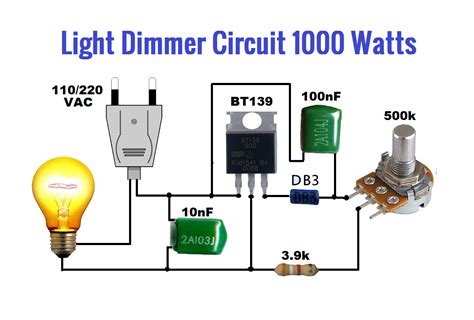
Abstract - This document presents the construction of a light dimmer circuit that utilizes the current-regulating properties of a triac. Tarun Agarwal is the Chief Customer Support Officer at Edgefx. 9KK - 10NF capacitor 2A103J - 100NF capacitor 2A104J - db3 diac - 500k resistor potentiometer. It uses a triac, diac and has a radio-frequency interference (RFI) noise suppression circuit built into it as well. Before we get start building a 1 Watt LED Dimmer circuit, first consider a simple circuit as shown in figure below. Yes, you want to sleep well. how much voltage u are giving to ic555 timer.
The Working Of Circuit • A light dimmer works by essentially chopping parts out of the AC voltage. So, if you can adjust brightness. At first, when mains is ‘on,’ the lamp is ‘off’. With three equal strings, the total current was 75mA and so we chose a transistor (BC547) with an Ic rating of 200mA – better safe than sorry. This dimmer circuit cannot be used to turn the LEDs all the way off or to full.
available dimmers, each and every circuit has its own dimmer to which it is permanently connected. The proposed dimmer circuit is designed, built and tested with
In this project, we will show how to build a light dimmer circuit. gr
Simple Light Dimmer Switch Circuit The circuit diagram shown above is an classic example of a light dimmer switch, where a triac has been utilized for controlling the intensity of light. Remote advising appointments can be made by contacting dxarts@uw. 0 Hz and an rms voltage of 120 V.
The Westek 6004BC Plug-in Touch Control Dimmer is The Westek 6004BC Plug-in Touch Control Dimmer is perfect for bedrooms, living rooms or any area where you need adjustable light.
Low Voltage Light Dimmer - A light dimmer is a means of controlling the "brightness" level of a lamp, in this application we will use a555 Timer to control the brightness level of a low voltage incandescent bulb of up to 60-Watts. Our Raitt Hall and McMahon Hall facilities will remain closed until further notice.
magazine. This automatic light dimmer circuit makes it possible to control a lighting system so that it turns.
In our test circuit, the resistors in the LED strings were chosen to provide a forward current of 25mA to the LEDs. The basic principle of light dimmer is based on phase control. By making slight modification with respect to the power dissipation, you can even implement this circuit with high-power LEDs for real-time use. This paper proposes a dimmer circuit that is suitable for incandescent bulbs, CFLs and LEDs. Imagine in your bedroom too bright. Some nights you want to read a book.
12V DC Light Dimmer Circuit Using 555 Timer IC.
IR Light Dimmer v.
These are many ideas of the AC light dimmer circuit. When AC mains is fed to the above circuit, as per the setting of the pot, C2 charges fully after a particular delay providing the necessary firing voltage to. fastpdf --
This simple 220V light dimmer circuit can be used to adjust the brightness of mains lights. You will probably find the dual time constant dimmer more stable at low light levels . When the dimmer is turned anticlockwise to a point where the filament glow is just visible, that point can be used as the reference point for measuring the voltage. We are going to create as simple of a light dimmer as may be possible Light dimmer circuit شرح pdf.
Light dimmer circuits related subject: Power electronics: 1200 Watt lamp dimmer circuit The circuit is a lamp dimmer circuit that is capable of controlling up to 1200 Watts.
Here is a very easy and useful schematic of an LED dimmer circuit. When it is fitted, and the light is switched on, the lamp does not come on fully for about 400 ms (which is not noticeable). Another NM cable connects from this dimmer box to the light fixture box. 1. It uses a triac, diac and has a radio-frequency int…
Here is the simple but effective project which control brightness according to our use from the unchanged light source. When AC mains is provided to the above circuit, as per the setting of the pot, C2 charges fully after a specific delay supplying the necessary firing voltage to the diac.
Off course the dimmed lamp will use less power than the full lamp . It also can be used to adjust the speed of AC motors.
This simple 220V light dimmer circuit can be used to adjust the brightness of mains lights. 1 ♥♥ This is diagram about IR Light Dimmer v. The circuit is using a famous voltage regulator IC LM317T. This simple triac dimmer can be used to control incandescent filament lamps up to 200W.
With conventional dimmer wiring using NM cable, a NM cable supplies line voltage from the electrical panel to the dimmer outlet box. A DC motor is a reactive load (inductive). where the pin 5 of ic555 timer is attached in the circuit?? i mean from where the control voltage input is taken to pin5 ???
Want a triac LED lamp dimmer circuit that can work with the new LED lamps; 20 LED array, 15 watts, 0.
Automatic Lamp Dimmer Circuit Received by Email - 09/28/2008. The heart of the circuit touch dimmer using triac is the S576 (IC 1) which provides an uncomplicated and elegant method to fire the triac. You'd likely fry the dimmer pretty quickly. 032 amps @ 120 VAC. In SCR light dimmers the firing angle is controlled as a result of which the waveform is distorted. 0025 amp) and is fairly linear all the way up to maximum, 120 VAC . This "light dimmer" circuit is connected to an ac generator with a frequency of 50. This has led to the words “dimmer” and “circuit” being used – mistakenly – interchangeably. On my powerstat, this lamp shows light ignition at about 36 VAC (.
A light dimmer is a means of controlling the "brightness" level of an incandescent lamp, in this application we will use a 555 timer to control the brightness level of a low voltage incandescent bulb of up to 60 watts. Different kinds of lighting devices are studied and tested with AC and DC sources. In the above design we seem to have missed one crucial point.
Using a Light Dimmer IC for AC Motor Speed Control - This circuit example uses LS7231 Light Dimmer IC (added 6/06) : Varying Brightness AC Lamp - In this circuit, an SCR is used to slowly vary the intensity of a 120 volt light bulb by controlling the time that the AC line voltage is applied to the lamp during each half cycle. All we will use for this circuit is a MOSFET, which acts as an amplifier, so that there is enough current to.